

1. Định nghĩa và bản chất kỹ thuật
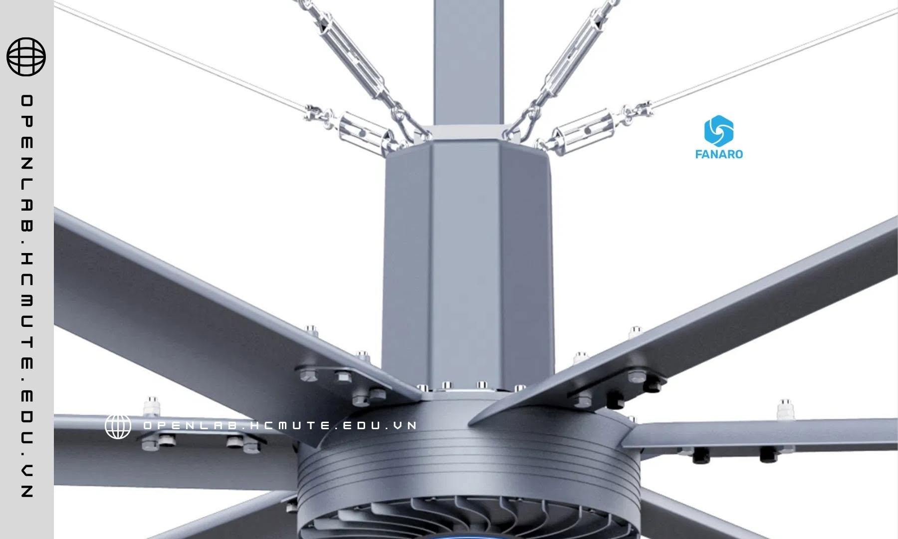
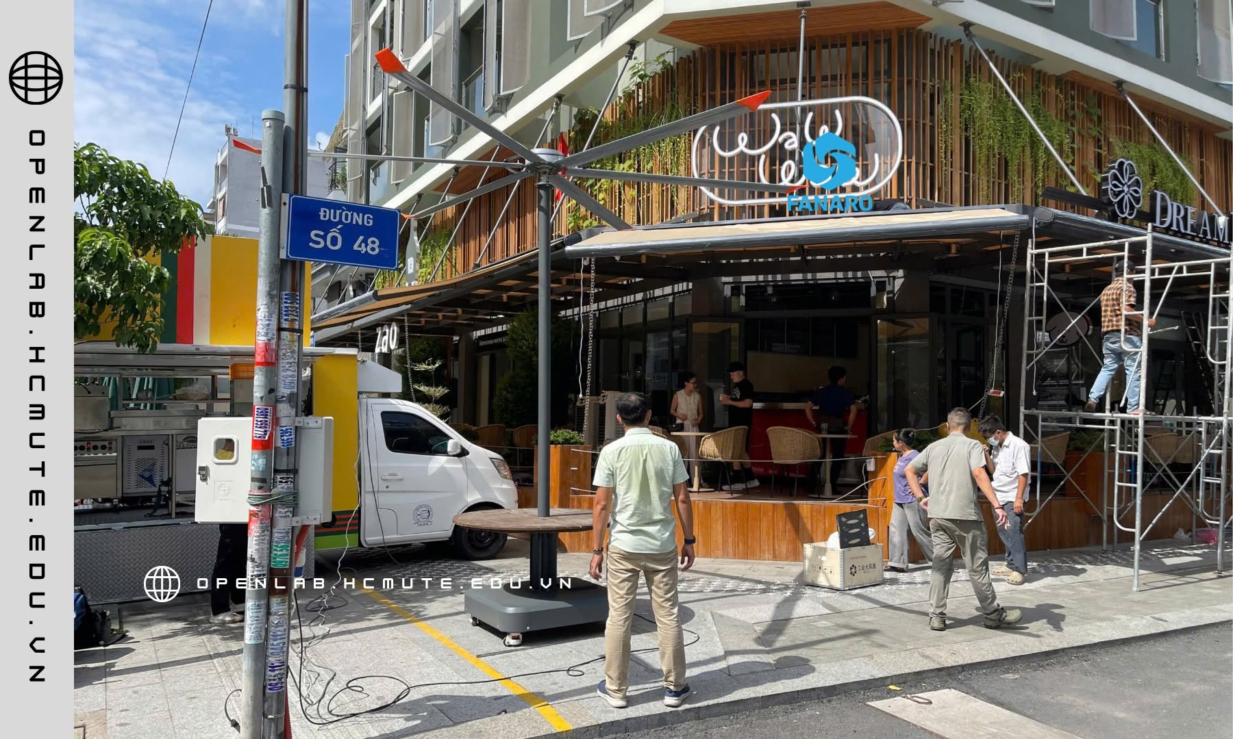
HVLS (High Volume Low Speed) là công nghệ quạt vận hành theo nguyên tắc: sử dụng cánh quạt có đường kính lớn (thường 3–7,3m), quay ở tốc độ rất thấp (30–60 vòng/phút), nhằm dịch chuyển một thể tích không khí cực lớn trên mỗi vòng quay. Đây là sự đảo ngược hoàn toàn triết lý thiết kế so với quạt công nghiệp truyền thống — vốn dùng cánh nhỏ, quay tốc độ cao (800–1500 vòng/phút) để tạo luồng gió mạnh nhưng tập trung trong phạm vi hẹp.
Về bản chất khí động học, hiệu quả làm mát của một quạt không chỉ phụ thuộc vào tốc độ luồng gió (velocity) mà còn phụ thuộc vào lưu lượng thể tích (volumetric flow rate – m³/phút) và diện tích vùng phủ (coverage area). HVLS tối ưu hai yếu tố sau thay vì chỉ tối đa hóa tốc độ gió cục bộ.

2. Phương trình lưu lượng và vì sao “quay chậm, cánh lớn” lại hiệu quả hơn
Lưu lượng thể tích không khí một quạt tạo ra được xấp xỉ theo công thức:
Q ≈ A × v
Trong đó Q là lưu lượng (m³/s), A là diện tích quét của cánh quạt (πr²), v là vận tốc gió trung bình qua mặt cắt quét.
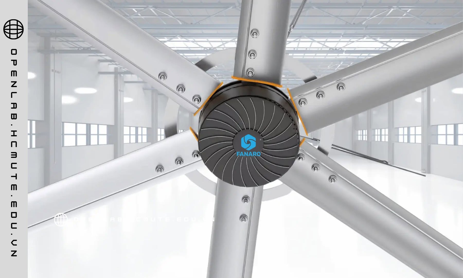
Vì diện tích quét A tỷ lệ với bình phương bán kính cánh quạt (r²), việc tăng đường kính cánh quạt tạo ra mức tăng lưu lượng phi tuyến tính rất lớn — một quạt đường kính 6m có diện tích quét gấp 4 lần quạt đường kính 3m, dù tốc độ quay chậm hơn nhiều. Đây là lý do một quạt HVLS cỡ lớn có thể tạo lưu lượng khí tương đương hàng chục quạt công nghiệp cỡ nhỏ cộng lại, trong khi vận tốc gió tại mỗi điểm trong vùng phủ lại thấp hơn nhiều, tạo cảm giác gió tự nhiên, dễ chịu thay vì luồng gió “xối” tập trung.
3. Cơ chế tạo cảm giác mát: hiệu ứng làm mát bay hơi (evaporative cooling), không phải hạ nhiệt độ không khí
Một điểm kỹ thuật quan trọng cần làm rõ: quạt HVLS — cũng như mọi loại quạt — không làm giảm nhiệt độ không khí thực tế trong phòng. Cơ chế tạo cảm giác mát đến từ hiệu ứng làm mát bay hơi trên bề mặt da (evaporative/convective cooling): luồng không khí chuyển động liên tục làm tăng tốc độ bay hơi mồ hôi và tăng hệ số truyền nhiệt đối lưu (h) giữa cơ thể và không khí xung quanh, theo định luật làm mát Newton:
Q = h × A × ΔT
Luồng gió càng ổn định và bao phủ diện rộng, hệ số h càng được duy trì đồng đều trên toàn bộ không gian, thay vì chỉ hiệu quả tại các điểm gần quạt như hệ thống quạt công nghiệp cỡ nhỏ. Đây là lý do nhiệt độ cảm nhận (perceived temperature, hay “wind chill effect” trong ngữ cảnh làm mát) tại các không gian dùng HVLS có thể giảm 5–8°C so với nhiệt độ không khí thực đo bằng nhiệt kế.
4. Hiện tượng khí động học: xoáy đầu cánh và tổn thất cảm ứng (induced drag)
Ở tốc độ quay cao, cánh quạt nhỏ tạo ra hiện tượng xoáy đầu cánh (tip vortices) mạnh — chênh lệch áp suất giữa mặt trên và mặt dưới cánh tại đầu mút gây ra dòng xoáy làm tiêu hao năng lượng dưới dạng nhiễu loạn (turbulence) thay vì lưu lượng khí hữu ích, đây gọi là tổn thất cảm ứng (induced drag). Tổn thất này tăng theo bình phương tốc độ quay.
Vì HVLS vận hành ở tốc độ góc thấp, tổn thất cảm ứng giảm đáng kể dù đường kính cánh lớn — đồng nghĩa với việc phần lớn năng lượng cơ học từ động cơ được chuyển hóa thành lưu lượng khí hữu ích thay vì tiêu tán vào nhiễu loạn đầu cánh. Đây là lý do kỹ thuật thứ hai (bên cạnh động cơ PMSM hiệu suất cao) giải thích mức tiêu thụ điện năng thấp của hệ thống HVLS so với lưu lượng khí tạo ra.
5. Biên dạng cánh (airfoil profile) và góc đặt cánh (pitch angle)
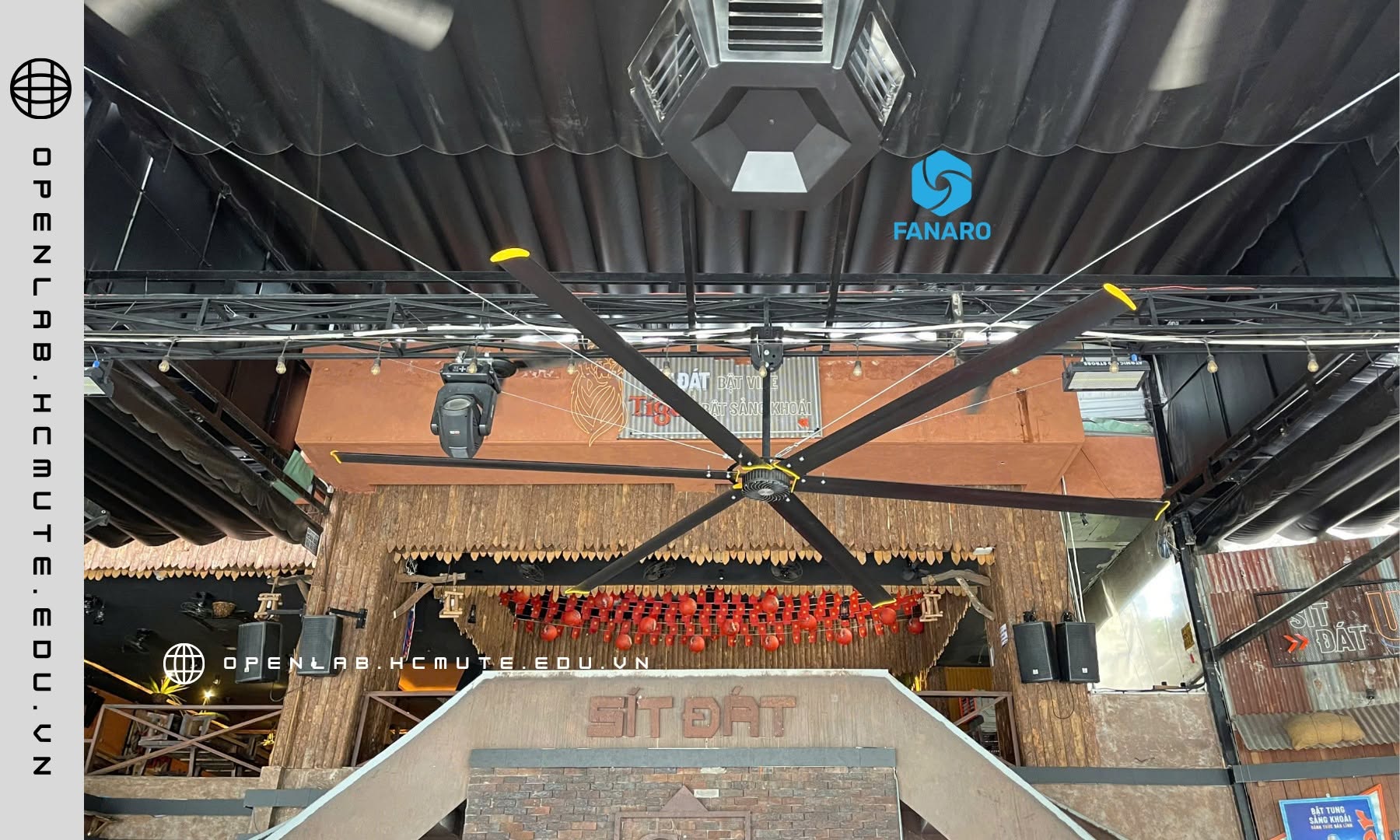
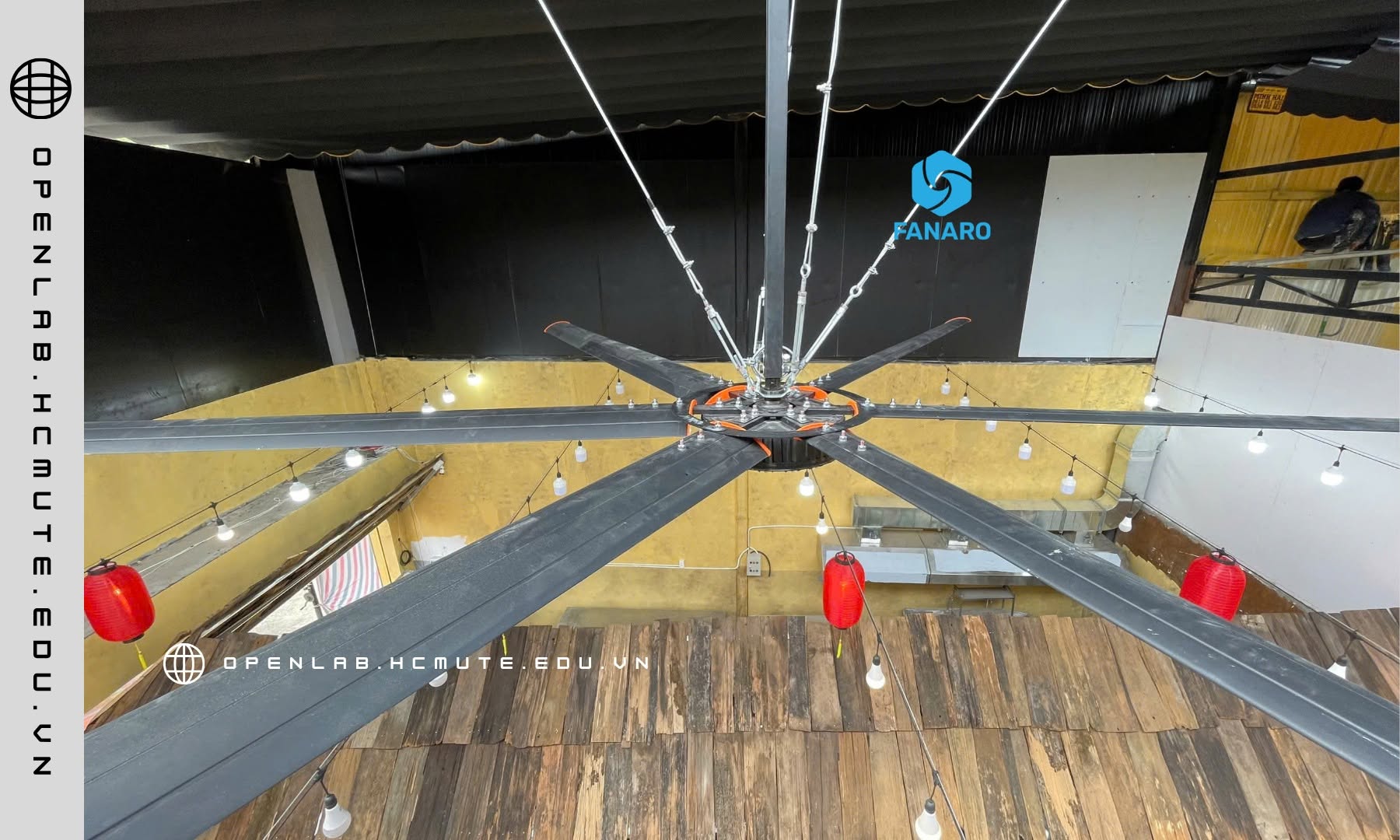
Cánh quạt HVLS thường được thiết kế với biên dạng khí động học (airfoil) tương tự cánh máy bay thu nhỏ — bề mặt cong bất đối xứng nhằm tối ưu hệ số nâng (lift coefficient) ở dải tốc độ góc thấp, khác với cánh quạt công nghiệp phẳng đơn giản chỉ tối ưu cho tốc độ cao. Góc đặt cánh (pitch angle) cũng được tính toán để tối đa hóa lưu lượng dọc trục (axial flow) mà không gây thất thoát năng lượng dưới dạng chuyển động xoáy tiếp tuyến (tangential/swirl flow) — một sai số thiết kế phổ biến ở các dòng quạt cánh lớn giá rẻ, gây rung lắc và giảm hiệu suất luồng gió thực tế dù đường kính cánh lớn.
6. Phân bố áp suất và vùng phủ đối lưu (coverage pattern)
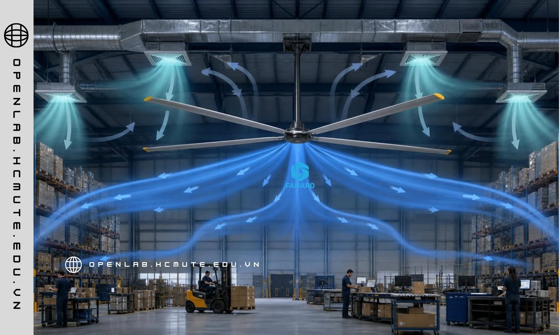
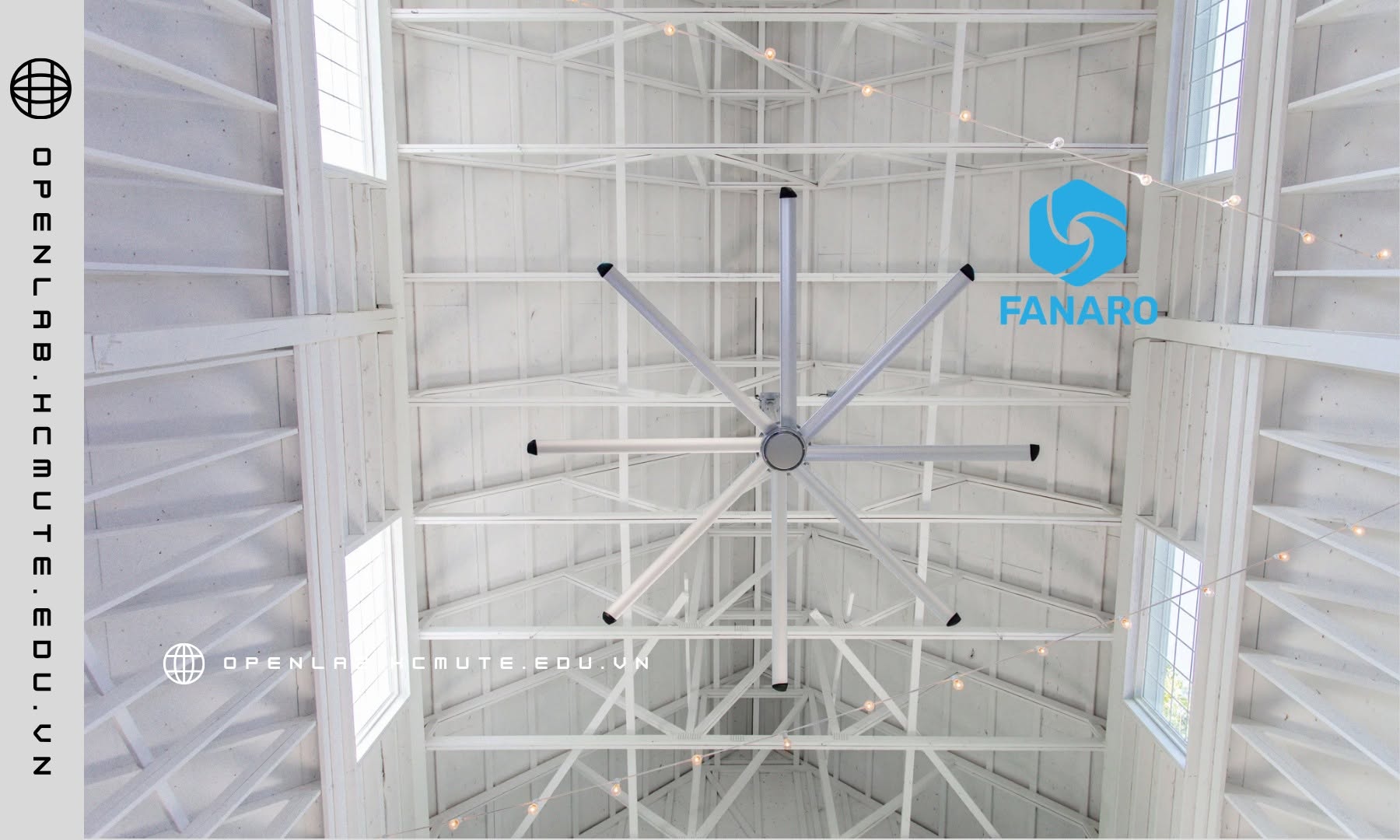
Khi luồng khí dọc trục từ quạt HVLS chạm sàn, nó tỏa ra theo hình nón (floor jet), tạo thành vùng đối lưu ngang lan rộng theo bán kính trước khi hồi lưu ngược lên trần theo chu vi không gian — đây gọi là mô hình đối lưu vòng lặp (recirculation loop). Bán kính vùng phủ hiệu quả trên sàn của một quạt HVLS thường đạt gấp 1,5–2 lần đường kính cánh quạt, tùy chiều cao lắp đặt và điều kiện không gian (chiều cao trần, vật cản, luồng khí chéo từ HVAC).
Đây là cơ sở kỹ thuật cho việc tính toán số lượng và khoảng cách lắp đặt quạt HVLS trong một không gian lớn — bài toán thiết kế đòi hỏi cân bằng giữa số lượng thiết bị tối thiểu và độ chồng lấn vùng phủ (overlap) đủ để tránh vùng chết (dead zone) không có luồng khí lưu thông.
7. Tương tác với tải nhiệt trong không gian công nghiệp
Trong nhà xưởng, kho bãi — nơi có nguồn nhiệt tỏa ra từ máy móc, ánh sáng, hoặc nhiệt bức xạ mái tôn — không khí nóng có xu hướng phân tầng (thermal stratification), tích tụ ở khu vực trần cao trong khi khu vực làm việc ở tầm thấp vẫn tương đối mát nhưng ẩm và tù đọng. Luồng khí dọc trục mạnh từ HVLS phá vỡ hiện tượng phân tầng này bằng cách liên tục trộn lẫn (destratification) lớp không khí nóng phía trên với lớp không khí phía dưới, giúp nhiệt độ trong toàn bộ không gian được đồng đều hóa thay vì tích tụ nhiệt cục bộ ở khu vực trần.
Đây là lý do HVLS còn được ứng dụng cả trong mùa lạnh (ở chế độ đảo chiều quay – reverse mode) để đẩy lớp không khí ấm tích tụ trên trần xuống khu vực làm việc, giảm tải cho hệ thống sưởi — dù ứng dụng phổ biến nhất tại Việt Nam vẫn là làm mát mùa nóng.

8. Kết luận kỹ thuật
Hiệu quả của công nghệ HVLS không đến từ việc đơn thuần “làm cánh quạt to hơn”, mà là kết quả của một bài toán tối ưu đa yếu tố trong khí động học: tận dụng mối quan hệ phi tuyến giữa diện tích quét và lưu lượng khí, giảm thiểu tổn thất cảm ứng nhờ vận hành ở tốc độ góc thấp, tối ưu biên dạng cánh cho dải tốc độ đặc thù, và tạo ra mô hình đối lưu vòng lặp có khả năng phá vỡ hiện tượng phân tầng nhiệt trong không gian lớn. Kết hợp với động cơ PMSM hiệu suất cao ở tầng truyền động, HVLS đại diện cho một hướng tiếp cận toàn diện trong bài toán quản lý không khí công nghiệp — nơi hiệu quả làm mát, mức tiêu thụ năng lượng và diện tích vùng phủ được tối ưu đồng thời, thay vì đánh đổi lẫn nhau như các giải pháp quạt công nghiệp truyền thống.

TECHNICAL ANALYSIS: HVLS (HIGH VOLUME LOW SPEED) TECHNOLOGY
1. Definition and Technical Fundamentals
HVLS (High Volume Low Speed) is a fan technology operating on the principle of using large-diameter blades (typically 3–7.3m) rotating at very low speed (30–60 RPM) to displace an enormous volume of air with every rotation. This represents a complete reversal of the design philosophy behind conventional industrial fans, which use small blades spinning at high speed (800–1,500 RPM) to create strong but narrowly concentrated airflow.
In aerodynamic terms, a fan’s cooling effectiveness depends not only on air velocity but also on volumetric flow rate (m³/min) and coverage area. HVLS optimizes for the latter two factors rather than simply maximizing localized air speed.
2. The Flow Rate Equation and Why “Slow Spin, Large Blades” Works
The volumetric airflow rate a fan produces can be approximated as:
Q ≈ A × v
Where Q is the volumetric flow rate (m³/s), A is the swept area of the blades (πr²), and v is the average air velocity through the swept plane.
Because the swept area A scales with the square of the blade radius (r²), increasing blade diameter produces a highly nonlinear increase in airflow — a fan with a 6m diameter has four times the swept area of a 3m-diameter fan, despite spinning far more slowly. This is why a single large HVLS fan can generate airflow equivalent to dozens of small industrial fans combined, while the air velocity at any given point within the coverage area remains lower, producing a gentle, natural-feeling breeze rather than a concentrated, “blasting” airflow.
3. The Cooling Mechanism: Evaporative Cooling, Not Air Temperature Reduction
An important technical clarification: HVLS fans — like any fan — do not actually lower the air temperature in a space. The sensation of cooling comes from evaporative/convective cooling at the skin surface: continuous airflow accelerates sweat evaporation and increases the convective heat transfer coefficient (h) between the body and the surrounding air, per Newton’s law of cooling:
Q = h × A × ΔT
The more stable and widely distributed the airflow, the more evenly the heat transfer coefficient h is maintained across the entire space, rather than being effective only near the fan, as with small industrial fan systems. This is why the perceived temperature (or “wind chill effect” in a cooling context) in HVLS-equipped spaces can drop by 5–8°C relative to the actual air temperature measured by a thermometer.
4. Aerodynamic Phenomena: Tip Vortices and Induced Drag Loss
At high rotational speeds, small fan blades generate strong tip vortices — pressure differentials between the upper and lower blade surfaces at the blade tip create swirling airflow that dissipates energy as turbulence rather than useful airflow, a phenomenon known as induced drag. This loss scales with the square of rotational speed.
Because HVLS fans operate at low angular speed, induced drag loss is significantly reduced despite the large blade diameter — meaning a greater share of the motor’s mechanical energy is converted into useful airflow rather than dissipated as tip-vortex turbulence. This is the second key technical reason (alongside high-efficiency PMSM motors) explaining the low energy consumption of HVLS systems relative to the airflow volume they generate.

5. Airfoil Profile and Blade Pitch Angle
HVLS blades are typically engineered with an aerodynamic (airfoil) profile similar to a scaled-down aircraft wing — an asymmetric curved surface designed to optimize the lift coefficient at low angular speeds, unlike the simple flat blades of conventional industrial fans, which are optimized only for high-speed operation. Blade pitch angle is likewise calculated to maximize axial airflow without dissipating energy into tangential (swirl) motion — a common design flaw in cheaper large-diameter fans that causes vibration and reduces actual airflow efficiency despite a large blade diameter.
6. Pressure Distribution and Coverage Pattern
As the axial airflow from an HVLS fan reaches the floor, it spreads outward in a cone shape (floor jet), forming a horizontal convection zone that expands radially before recirculating upward along the perimeter of the space back toward the ceiling — a pattern known as a recirculation loop. The effective floor-level coverage radius of an HVLS fan typically reaches 1.5–2 times the blade diameter, depending on mounting height and space conditions (ceiling height, obstructions, cross-drafts from HVAC systems).
This forms the technical basis for calculating the number and spacing of HVLS fans required in a large space — a design problem that balances minimizing equipment count against ensuring sufficient coverage overlap to avoid dead zones with no air circulation.
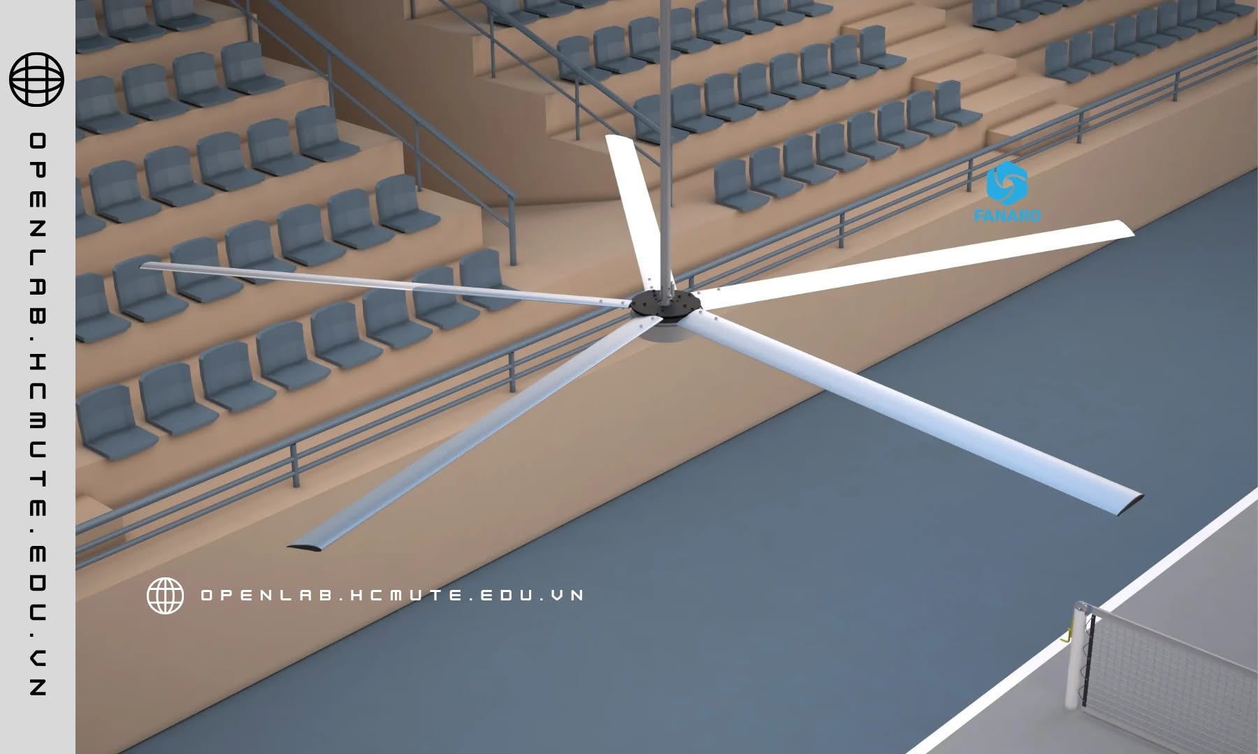
7. Interaction with Heat Load in Industrial Spaces
In warehouses and factories — where heat is generated by machinery, lighting, or radiant heat from metal roofing — hot air tends to stratify (thermal stratification), accumulating near the high ceiling while the working level below remains relatively cooler but stagnant and humid. The strong axial airflow from HVLS fans breaks up this stratification by continuously mixing (destratification) the hot upper air layer with the lower air layer, helping to equalize temperature throughout the space rather than allowing heat to accumulate near the ceiling.
This is why HVLS technology is also applied during colder months (in reverse-rotation mode) to push warm air that has accumulated near the ceiling back down to the working level, reducing the load on heating systems — although in the Vietnamese market, the dominant application remains hot-weather cooling.
8. Technical Conclusion
The effectiveness of HVLS technology does not come from simply “making the blades bigger,” but from solving a multi-factor aerodynamic optimization problem: leveraging the nonlinear relationship between swept area and airflow volume, minimizing induced drag loss by operating at low angular speed, optimizing blade profile for a specific speed range, and generating a recirculation flow pattern capable of breaking up thermal stratification in large spaces. Combined with a high-efficiency PMSM motor at the drivetrain level, HVLS represents a comprehensive approach to industrial air management — one where cooling effectiveness, energy consumption, and coverage area are optimized simultaneously, rather than traded off against one another as in conventional industrial fan solutions.
Bình luận